Story & Photos By Jim Clark (The Hot Rod MD)
Many articles have been written about installing a new or modifying an existing braking system. But they usually just show a diagram of where the lines need to be routed and which valves and hoses are need to make the system function. However, when it comes time to actually install the lines and other components it becomes apparent that there are a lot of connections to be made between all of these components and that it will require a variety of fittings to make this happen.
Choosing the necessary fittings is made much easier if a simple drawing of the brake system is made showing the routing of the lines and placement of components. The drawing doesn’t have to be as elaborate as this one that I did for my roadster project. As long as the components and lines are represented it is possible to determine what fittings are needed at each connection point.

The car in the drawing has a single-chamber master cylinder with drum brakes front and rear. It only needs one residual pressure valve (10-lb) and a proportioning valve for the rear brakes. Lines are 3/16-inch, 45° double-flared with -3 AN braided hoses in place of the original rubber type hoses. More elaborate systems will have more components but the process of selecting the connection hardware is the same.

The use of AN fittings requires the switch to frame connectors like this one from Godman. It bolts through the frame or a mounting bracket with the AN fitting on the one side and either a pipe threaded hole or inverted flare opening on the other. They are available in different lengths depending on the thickness of the frame.

Tees or elbows with female-inverted-flares (FIF) and in some cases like this one with male-national-pipe-thread (MNPT) serve as transitions between frame connectors and other system components.

At the left front a frame connector is bolted into a bracket with a dual-inlet 3/16-inch FIF Tee that screws into the fitting via 1/8-inch MNPT. Braided -3 AN hose routes out to the left front brake cylinder. Line going forward connects to the right front brake via the same type frame connector but with a 90° 3/16-inch FIF fitting connected by a 1/8-inch MNPT branch.

A three-inlet 3/16-inch FIF Tee serves to continue the line to the rear while providing an inlet point for fluid coming from the master cylinder. Fittings like this with a mounting bracket are found on many OEM vehicles and are available from dealers, parts houses and brake specialty suppliers.
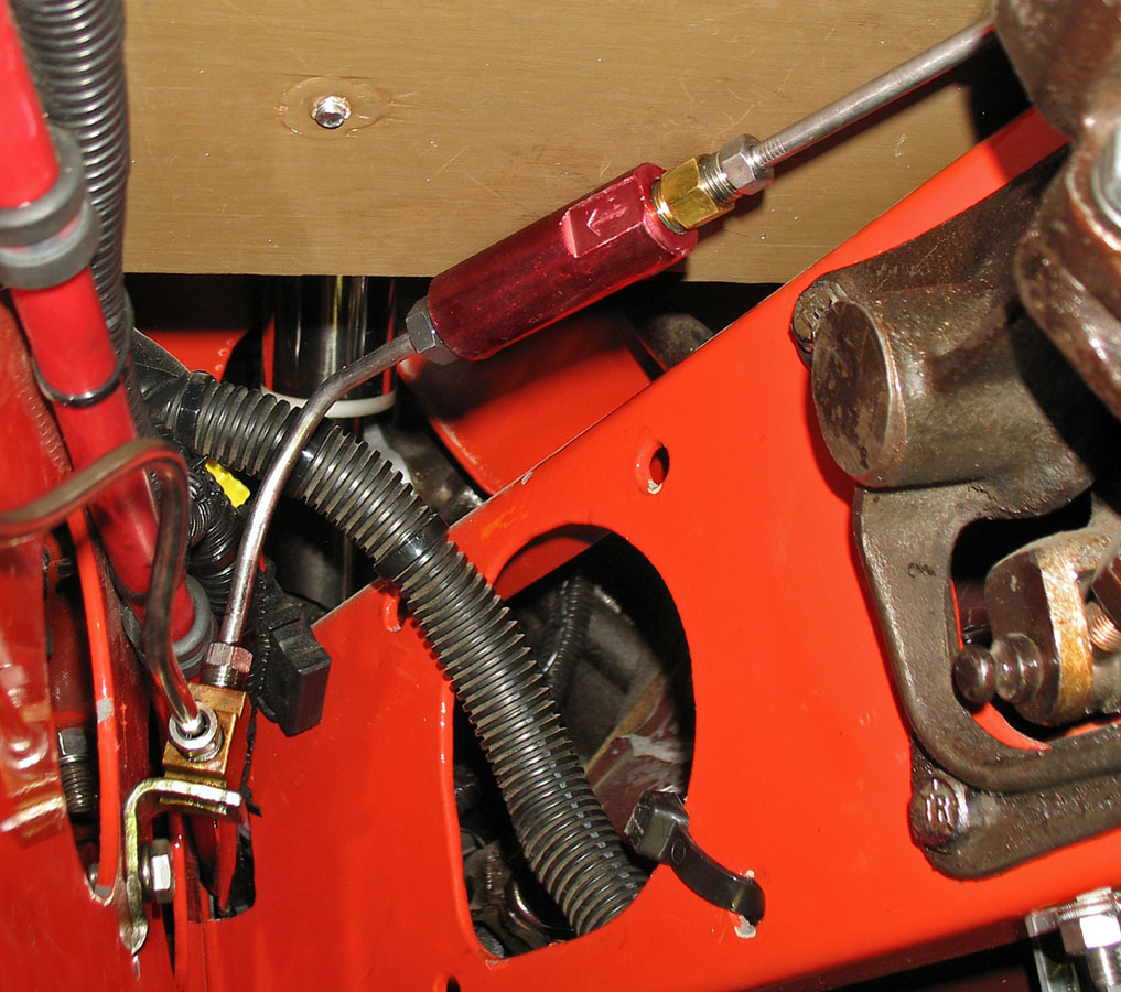
This residual pressure valve (10-lb) retains a light pressure in the line to help prevent a spongy pedal or lag in brake application. It should be installed as close as possible to the master cylinder and is directional, as indicated by the arrow showing the direction of flow. The fitting at the inlet is an adapter with a 3/16-inch FIF inlet and a 1/8-inch MNPT branch. The line connects with a 3/16-inch flare nut on the 45° flared line. Outlet has its own flare nut for the 45° flared line.

Line connects to the outlet of the master cylinder via the same type adapter with a 3/16-inch FIF inlet and a 1/8-inch MNPT branch. The line connects with a 3/16-inch flare nut on the 45° flared line. Early Ford style multi-port fitting at the rear of the master cylinder provides a mounting point for the brake switch.

This adjustable proportioning valve is mounted in the line going to the rear brakes. It allows the reduction or increase in pressure to the rear brakes necessary when trying to achieve a balance in braking between the front and rear. It uses the same adapters and flare nuts to make the connections as those on the residual pressure valve.

The brake line continues to the rear, connecting to another through-the-frame fitting mounted to the crossmember via an L-bracket. It differs from the others in the system in that it has a 3/16-inch FIF inlet instead of a 1/8-inch FNPT female inlet.

A -3 AN braided line connects to the through-the-frame fitting supplying fluid to the rear brakes via lines attached to the rear end.

The 90°-ended -3 AN braided hose connects to another through-the-frame fitting with a threaded Tee like the one at the left front brake. Bracket is the stock mount on the original Buick rear end.

View from the rear shows how the Tee screws into the through-the-frame fitting and flare nuts attach the lines going out to each wheel cylinder. Rear wheel cylinders accept the 45° flared line with a 3/16-inch flare nut.


A male inverted flare adapter of the correct thread size like the one shown from Pure Choice is needed at the front wheel cylinder to accept the -3 AN hose. For the mid-50s Ford F-100 wheel cylinder shown here I had to use a similar type of fitting sealed with a copper washer because one of this type with the correct length was not available.
This system was pretty basic because it has drum brakes and a single-stage master cylinder. Systems with disk/drum combinations or all-disk brakes and ones with a dual-stage master cylinder require more components and lines but are plumbed using the same procedures. Brake component suppliers usually have free tech lines offering advice but you need to know how your system is configured to get the correct components for your application.
You will encounter suppliers that will sell systems with components that do not actually comply with the federal regulation for braking systems. They may work as well but the ones using steel or brass fittings and 45° double flares like those used by OEM manufacturers, in my opinion, are the easiest to seal and meet the standards set by those federal regulations.
A good 45° double flare will seal without tightening the flare to extremes but a flare with small cracks or irregularities will not seal no matter how much they are tightened. A light coat of anti-seize on the flare in the flare nut can reduce friction with the back of the flare allowing it to turn when tightening. I have seen articles recommending that Teflon tape or thread sealer be applied to the threads of the flare nut but this accomplishes nothing as the threads are only holding the flare and sealing nothing. Some Locktite dry-stick sealer is ok for sealing on pipe threads in the system but Teflon tape is never recommended for brake systems because it gets cut by the threads during installation and can get into the system causing restrictions or blockages.
Brake and steering systems are arguably the two most important ones for safety on a vehicle. Taking the time to design them correctly is a top priority. When installing or having a brake system installed it is a good practice to talk to a number of reliable sources before proceeding with it.