Calibrating a Speedometer
Story & Photos By Jim Clark (The Hot Rod MD)
Many of us “gearheads” have had the experience of being pulled over by our friendly local law-enforcement officer and being told that we were exceeding the posted speed limit. We inform him of the fact that we couldn’t be speeding because our speedometer indicated that we were doing exactly what the posted speed limit is. That argument never works though, because by design the vehicle’s speedometer is accurate by law, or international agreement to about plus-or-minus 10%.
Speedometer Error
This speedometer error is due mainly to variations in tire diameter, tire wear, tire temperature, pressure and vehicle load. Vehicle manufacturers usually calibrate speedometers to read high by an amount equal to the average error. This is done to ensure that their speedometers never indicate a speed lower than the actual speed of the vehicle, in an attempt to ensure they are not liable for drivers violating speed limits.
United States
Federal standards in the United States allow a maximum 5 mph error (plus-or-minus) at a speed of 50 mph on speedometer readings for commercial vehicles (CFR-393.82). Aftermarket modifications, such as different tire and wheel sizes or different differential gearing, can cause speedometer inaccuracy. Private passenger vehicles generally adhere to the international standard of never reading below the actual speed of the vehicle but the indicated speed must not exceed 110% of the actual speed. So the accuracy is always subject to many variables.
A speedometer/odometer is basically an instrument that indicates how fast the vehicle is traveling at a given moment while the odometer records an ongoing record of how far the vehicle has traveled. Knowing how fast the vehicle is traveling provides vital information to allow safe operation of the vehicle and can help to avoid a chance meeting with a friendly, or not-so-friendly law-enforcement officer. The odometer alerts us to when necessary service intervals have arrived.
For many years vehicles have been equipped with mechanical drive speedometers and they continue to be the choice of many individuals building or restoring a hot rod. New cars are all equipped with electronic speedometers, both analog and digital, and most of the original-equipment and aftermarket instrument suppliers are now featuring electronic speedometers as their main lines.

Speedometer/odometer on the left is a mechanical cable-driven VDO Cockpit series instrument like hot rod type vehicle have been equipped with for many years. Speedometer/odometer on the right is a VDO Cockpit series of the same style but fully electronic,
If you are using the original instrument cluster from the vehicle you will probably want to retain the original mechanical speedometer. However, some companies are offering to convert your original gauge array to electronic while keeping the original look of the panel.
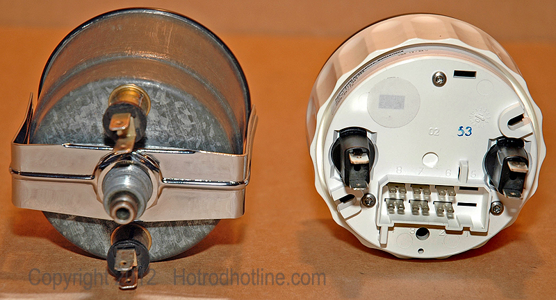
Rear view of both instruments, side-by-side, shows the cable hookup for the mechanical unit and the electronic input plug receptacles for the other unit.
Whichever type of speedometer that you use when building a modified vehicle it will need to be calibrated to compensate for any change in tire size or gear ratio. The mechanical, cable-driven speedometer can be corrected by replacing the gear or gears that are located on the output shaft of the transmission or with an externally mounted ratio adapter.
Mechanical Speedometer
For over a century the mechanical (eddy current) speedometer has been used and is still in widespread use. A rotating flexible cable usually driven by gearing linked to the output of the vehicle’s transmission inputs its signal. It was the only type commonly used until the 1980s and the appearance of electronic speedometers.
When the vehicle is in motion, a speedometer gear assembly at the rear of the transmission will turn a speedometer cable that then turns the speedometer mechanism itself. A small permanent magnet driven by the speedometer cable interacts with a small aluminum cup attached to the shaft of the pointer on the analogue speedometer. As the magnet rotates near the cup, the changing magnetic field produces “eddy” currents in the cup, which then produces another magnetic field. The effect is that the magnet exerts a torque on the cup, "dragging" it, and thus the speedometer pointer, in the direction of its rotation with no mechanical connection between them.
The torque on the cup increases with the speed of rotation of the magnet. Resistance to movement is created by the spring trying to hold the pointer at zero. At a given speed the pointer will remain motionless and pointing to the appropriate number on the speedometer's dial. This is fixed at a preset number of revolutions per mile (usually 1,000 rpm per mile). You will need to determine what is the correct number for your application. At this point the corrections need to be made by allowing for the variations in the vehicle from stock.
Calibrating a Mechanical Cable-driven Speedometer
One of these methods can be used to determine whether your speedometer is accurate or needs to be recalibrated.
Method-1:
A—Find a measured mile. Use the mile markers on an interstate highway or a speedometer test zone. Interstate highways have markers for each mile and some state or county roads have markers that can be used if you pay close attention to the tenth-of a-mile markers.
B—Check the odometer reading, in miles and tenths of a mile, as you pass a mile marker and then check it again as you pass the next mile marker.
C—Check it again two more times to be sure that your reading is accurate.
Method-2:
A—Unscrew cable end at the speedometer head.
B—Attach a flag on the end of the flexible cable formed from a piece of tape or by using a paper clip.
C—Measure a distance of 52-feet 9-1/2-inches and mark at each end with chalk or a piece of tape.
D—Roll the car up to the first mark making sure that the cable has begun to turn. You will probably need someone to help by keeping track of the cable turning.
E—Put a piece of tape on the side of the tire to align with the first mark. Push or drive from the first mark to the second mark.
F—Count and record the number of full turns and tenths of a turn that the cable makes. Ten full turns is correct for domestic cars. Note how many tenths of a turn, either over or under ten full turns, that the cable makes.
G—Repeat the test two more times to verify the accuracy of the results. From those results a speedometer specialist can build a ratio adapter for the vehicle.
Method-3:
Write down the transmission type, number of teeth on the speedometer drive gear in the rear of the transmission, number of teeth on the speedometer driven gear, the rear end ratio and the diameter of the rear tire. Call or take this information to the speedometer specialist and they can use the information to build the correct ratio adapter for your vehicle.

The drive gear (at the top of the photo) for the speedometer is mounted onto the transmission output shaft within the tailhousing. White gear at the left is the driven gear on the governor. It is not part of the speedometer drive-system.

Speedometer driven gear is held in place in the tailhousing of the transmission by this O-ringed insert. Large gear is the driven gear (38 tooth) for my GM Turbo 400 transmission. Smaller gears in the foreground are for a Ford C-6. They are from the left: Blue-20, Blk-22, Red-21, Grn-22, Wht-19 and oil-discolored Wht-19 teeth replacement gears for changing the ratio. I used the Brn-18 tooth gear (not shown) in the Ford van. A number of gear sets are probably available for your application.

Speedometer drive is held into the transmission opening by a bolt and clip. Normally the cable is attached to this drive.

When a change in the combination of drive and driven gears in the rear of the transmission will not achieve the desired output speed or are more work than you want to go through to make the change then a ratio adapter will work as an alternative. It accepts input from the transmission and through a gear set outputs the desired cable revolutions.

View from this angle shows the cable-drive side of the ratio adapter that connects at the transmission and the cable connection point at the left.
Electronic Speedometers
Many modern speedometers are electronic, in designs derived from earlier eddy-current models. They consist of a rotation sensor mounted in the transmission that delivers a series of electronic pulses whose frequency corresponds to the (average) rotational speed of the driveshaft, and therefore the vehicle's speed, assuming the wheels have full traction. The sensor is typically a set of one or more magnets mounted on the output shaft, or a toothed metal disk positioned between a magnet and a magnetic field sensor. As the part turns, the magnets or teeth pass beneath the sensor, each time producing a pulse in the sensor as they affect the strength of the magnetic field it is measuring. In more recent designs, some manufacturers rely on pulses coming from the ABS wheel sensors.
An ECU (mini computer) converts the pulses to a speed and displays this speed on an electronically controlled, analog-style needle or a digital display. Pulse information is also used to increment the odometer in place of it being turned directly by the speedometer cable.
Electronic speedometers are simpler to calibrate because it usually just involves following the calibration instructions for the given make and model of unit by manipulating the speedometers ECU (mini computer) via the adjustment controls.
Calibrating the Electronic Speedometer
Calibration of the VDO speedometer with LCD Display is a relatively simple procedure, and can be accomplished in any of three ways:
1—Automatic calibration when driving on a road with the exact distance of one-mile clearly defined; or on a dynamometer…
2—By the input of the known pulse-per-mile (kilometer) for the vehicle and sensor being used with the speedometer…
3—Using a reference point for adjustment or fine-tuning.
You gain access to the calibration functions by pressing the button on the front of the speedometer and holding it in while you turn on the ignition. As you continue to hold in the button, the display will change… scrolling through the three calibration methods and stopping on each one for about two seconds.
Calibration modes as displayed on the speedometer’s LCD
The display lists the auto-calibrate mode as “ AutOCL”; the pulse-per-mile mode as “PuLSE”; and the reference/fine-tune mode as “AdJuST”. When you see the method you wish to use, let go of the button and that function will be enabled.
1—Auto-calibration is the simplest of the three methods. However, the auto-calibration function can be used successfully only on: 1—A road with the distance of one mile actually designated by markers or 2—On a dynamometer.
After selecting the proper mode upon starting the vehicle you continue holding the button in for about three-seconds. The readout will then display “bUttOn”. When you are ready to begin your calibration run, press the button again. The display will now begin flashing the word “StArt”.
Now drive the reference distance between the markers for one mile. When you have gone exactly one mile, press the button again. If the electronic impulse rate detected by the speedometer’s microprocessor is within the calibration limits of 500 to 399,999, the rate will be shown on the LCD display. The calibration process is complete. If the electronic impulse rate is not within range, the following message: “F O.O” will be displayed and you will have to repeat the calibration process until it is in range. Most will use this method.
2—Manual Calibration with a known value. If you know the exact calibration value for the vehicle and type of sensor you are using (pulse-per-mile or kilometer-per-mile), you may use that value to manually calibrate the speedometer.
The instructions included with the speedometer give a detailed description of the procedure but the basic process involves selecting the right mode, holding the button until “PuLSE” is displayed then entering the correct value by changing the default code “50000” to the value for your specific application.
3—Manual Calibration (Fine Tuning) You can fine-tune the calibration of the speedometer’s analog display (the pointer showing miles-per-hour or kilometers-per-hour) by using speed test equipment and the “AdJuSt” function on the LCD readout. The included instructions give details about this procedure but the bottom line for this procedure is that to manually calibrate the pointer on the analog display using this method the vehicle has to be on the dynamometer at a specified speed. This method will deliver the most precise readings but most of us will not have access to this equipment and the variance in accuracy from the other methods will not be significantly different enough to warrant the cost of doing this additional step.

The VDO electronic speedometer that I am using in my roadster receives its signal from this hall-effect device via the three-wire cable that plugs into it. Plug on the speedometer end completes the connection.

I was unable to attach the hall-effect device directly to the transmission due to clearance issues between the crossmember and the device. I bought this one-to-one ratio 90° adapter to provide the needed clearance.

The ratio adapter in this case was only needed to change direction for clearance, however one with the correct ratio can be used to compensate for an out of calibration speedometer.
So you need to evaluate the particular details that apply to your vehicle and decide what course you need to take to bring its speedometer into calibration. Most speedometer errors come from a mismatch in the tire height, the rear-end gearing, or the drive-and-driven speedo gears combination in the transmission.
The vehicle’s tires can almost be thought of as a third type of gearing. For example a vehicle equipped with 295/35-18 tires, which have a circumference of 82.1 inches, would travel 82.1 inches for every complete revolution of the wheel. If the vehicle had larger tires, it would travel farther with each revolution of the wheel, which would be like a higher gear. If the vehicle had smaller tires, it would be like a lower gear.
With the gear ratios of the transmission and differential, and the size of the tires, it becomes possible to calculate the speed of the car for a particular gear at a particular engine RPM.
Therefore, it is possible to determine the distance the car will travel for one revolution of the engine by dividing the circumference of the tire by the combined gear ratio of the transmission and differential. Which method you choose will be dictated by your specific vehicle configuration. A good shop that specializes in speedometer and instrument repair is your best source of information in your quest to solve the calibration problem.
Another Option available from Classic Instruments is their new, award winning, SkyDrive Unit.
Calibrate your speedometer in less than a minute and you don't even have to leave your driveway! Sky Drive is the world's most accurate electronic speedometer sending unit. No need for ECU convertors or pulse signal generators screwed onto your transmission. The new Sky Drive uses GPS Satellite signals to operate your electronic speedometer. It updates 10 times per second and with one push of a button it's ready to go.
.jpg)
Get the Details at Classic Instruments