2003-2007
|
Segment 1: October 2003 This is the beginning of a series of articles in which we will follow the progress of Cruisin Products as they build a Rats Glass '32 Ford Roadster. We hope to provide some high quality step by step commentary so as to show you each of the steps in building a car. These steps, we feel, may help our visitors as they work on their own. |
|
|
|
|
We want to start with a bit of information about Bob Brace and Cruisin Products. Bob has been involved in building frames and chassis extensively over the last 20 years. He specialized in '32--'40 Ford frames in the early ‘80's and has added the current additional offering of ‘40-’41 Willys, ‘37-’29 Chevy and some Mercury frames and chassis in recent years. Bob has worked with the stamped rails in the ‘80's from The Deuce Factory and the early offering of the welded rails from Dave Gails, Just A Hobby. Recently he built frames and chassis using A.S.C. stamped rails and welded frame rails from Curbside Hot Rod Parts. Bob says his experience has taught him a few points in the preparation and eventual building of frames and chassis that will be helpful to others. He is not acting as a spokesperson for one company or product but will offer his opinion of the products being utilized to build this online project….. So on to the shop ………. |
|
|
||||||||||||||||||||

|
|

|
|

|
|

|
|
|
||
 |
 |
||
|
|
|
|
These are some of the points I check in frame rails before the rails go to the frame fixture. These stamped rails have all the finer points that until now could only be found in the hand made welded rails. These rails look excellent so far but the frame fixture will be the real test. The next segment will cover the rails being positioned in the frame fixture and the installation of our Mounting Block System. |
|
|
|
|
|
|
Well that's it for stage 1 of the Cruisin Products Roadster project. We will be adding more as they proceed on the car and look forward to providing an informative and enjoyable series for our visitors. If you would like more information on the products from Cruisin Products visit their website atwww.CruisinProducts.com Email Bob at [email protected] or call them at 313-538-3586. They're great folks ! |
|||
|
Segment 2: Novermber 26, 2003 We left the last segment giving the new frame rails a good going over and checking certain aspects before going to the frame fixture. |
|
|

|
|

|
|

|
|

|
|
|
 |
|
|

|
Now that the rails are tack welded in the fixture, we move on to installing the Mounting Block System. This system will enable the customer to mount all times to the finished frame. We install metal blocks that will be positioned behind the boxing plates. |
|
|
|
 |
|
|

|
|

|
|

|
|

|
|
|
|
That's a wrap for another installment of this cool build up from the folks at Cruisin Products…. We hope you got some tips that will help you with your projects this winter. Check back next month for another installment.. To contact Cruisin Products you can visit their websitewww.CruisinProducts.com Email Bob at [email protected] or call them at 313-538-3586. They're great folks ! |
|
Segment 3: December 31, 2003 We hope everyone had a great Christmas and a Safe Celebration of the New Year. In this segment of our '32 Build up we'll box the frame rails. This process is aligning plates to the outside edges of the frame rails. I drew a diagram illustrating the proper fitting of a boxing plate to the outside of the frame rail. The boxing plates from Dearborn Mfg. has the rear C that lines up to the frame rails. I cut the boxing plates in two pieces for easier installation. |
|
|
|
 |
|
|
|
 |
|
|
|
 |
|
|

|
|
|
 |
|
Now that the pieces are welded you want to check the fit once again before we start welding. What we found was the cutting and welding did improve the overall alignment, but we still have a small area at the front we need to address. We start by clamping the plate for the best all around alignment. Tack weld the plate everywhere it aligns properly. Tack weld right up to the spot the plate runs off again. I use a torch to heat the side of the plate so the plate will move in the opposite direction. Once the plate moves to the proper location, clamp in place. Resume tack welding the boxing plate to the frame rail. |
|
|
|
|
|
|
|
|
|
|
|
|
|
|
|
 |
|||||||||||||
 |
|||||||||||||
 |
|||||||||||||
 |
|||||||||||||
|
Take your time in tack welding the plates in place. Check the heat build up in the rail. I use my hand and hold it above the rail to check the heat. You do not want the heat to be so hot in the rail that you would burn yourself. Let the rail cool down before welding anymore if it is too hot. Start on the other rail while the first rail cools. Remember to alternate the welds, top to bottom. Skip along the edges as you weld the plates in place. This process takes a while to completely weld the boxing plates. TAKE YOUR TIME. Don't hurry this process. You want a boxed frame rail free of distortion. |
|||||||||||||
 |
|||||||||||||
 |
|||||||||||||
|
|
|
|
When you finish welding the edges, grind the corner to the finish you want, square or round. When you have completed the boxing process you will have a new appreciation for the time and work involved in welding a frame. |
|
|
|
|
|
|
|
|
We will be working on this project through the winter and will bring you updates at least once a month. Remember … You'll find lots of great products, including the ones used in this project at Cruisin Products. Check out their web site. |
|||||
|
Until Next Time…. Keep Roddin ! |
|||||
|
Segment 4: January 30, 2004 We start this segment with the frame rail edges, they should look like the edges in the pictures. Be careful not to grind away the weld that holds the boxing plate in place. That’s why I square the welded edges of the boxing plates. You can round the edge with a hand file to eliminate the sharp corner. |
|
|
|
 |
|
 |
|
 |
|
 |
|
 |
|
|
|
|
|
You can see in the pictures how we finish the welded edges. Again take your time. If you grind the weld too deep you will be re-welding the edge. Check out the reflection of the edges in the pictures. |
|
Now that the boxing plates are finished, let’s move on to the front crossmember. Dearborn Manufacturing, the good people who stamped the ‘32 frame rails we are using in this project have developed a couple of new front crossmembers. They now offer their own version of the popular Model A crossmember and a flat front crossmember. We choose the flat front crossmember. |
|
|
|
 |
|
|
|
 |
|
|
||||||||||||||||||||||||||||


|
|
|
|
Study the pictures and send us any questions you might have at Cruisin Products !!! |
|
With the front crossmember welded in place we move to the installation of our X member kit. The kit is built with 1.5” round tubing. There are 4 main rails. Two top and two lower main rails. The top rails are the longer pair. The lower pair are shorter so the exhaust can be routed through the X member and not have to pass under the front legs. The top rails are laid out with a couple pieces of rectangular tubing across the frame rails (see photo). The measurement between the main rails will depend on the engine / trans combination. Usually a spacing of 14.5” between the main rails will be fine for most applications. We will be using a Turbo 350 in the car, so the 14.5” measurement will work. You can determine the measurement you may need by checking the width of your trans. Remember to leave room for the actuator cable or linkage. You can see how we transfer the vertical plane that will give the cut lines. We do this for the top main rails. Once the rails are cut and final fitted, they are tacked welded in place. |
 |
|||
 |
|||
 |
|||
 |
|||
|
With the top main rails tack welded we start on the lower main rails by positioning them over the main rails. Again using a straight edge mark the cut lines. Once the lower rails are cut we roll over the frame fixture and position the lower rails for tack welding. The lower rails are positioned by the short verticals in the kit. With the verticals in place the rails are clamped. Again we check to make sure that everything is still level. Satisfied we tack weld the lower rails in place. At this time the verticals are not tack welded. They remain unwelded till their final position is determined. |
|
|
|
|
|
|
|
 |
|||||
 |
|||||
 |
|||||
 |
|||||
 |
|||||
 |
|||||
 |
|||||
|
We will tackle the rear crossmember in the next segment. Until then check out our web site for other custom installations of our X member kit. At Cruisin Products !!! |
|||||
|
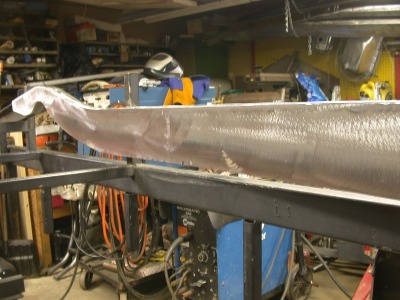
Segment 5: March 5, 2004 We have taken a different direction with this installment. This is suppose to be the segment installing the rear cross-member. As many projects go, we have changed direction to the other end of the frame and will be working on the front spring C notches. You can see in the picture the front spring in the flat front cross-member. The frame is positioned upside down. After making sure the spring is in the correct position we start the layout of the rails to be altered. |
|
|
|
 |
|
|
|
|
Lines are spaced equally from the spring on the bottom of each frame rail. We then stand the frame on end and determine the depth of the C notch to be installed. |
|
|
|
|
|
|
|
|
|
|
|
 |
|||||||||
 |
|||||||||
|
Cut the rough opening and check to make sure the angle cuts match each other, outside to inside of each frame rail. A die grinder and wheel works great. If you have a reciprocating saw that will work as well. |
|||||||||
 |
|||||||||
 |
|||||||||
 |
|||||||||
|
This is where we do things a little different. When we build the C notch in the frame rails, the front and rear angle inserts are welded from the bottom of each rail, past the horizontal cut that forms the C notch to the inside face of the top of each rail. Whooooa, read that again slow and take a look at the picture. Remember at this point the frame is again upside down. |
|||||
 |
|||||
|
I hope you could see what I tried to explain in that last picture! After the angled inserts are welded in place we fit a horizontal piece to finish the C notch fabrication. That is welded in place. Check the picture and you see the fully welded C notch before grinding. |
|||||
 |
|||||
|
|
|
|
Grind the welds and roll the edges, all around the C notch. If you need to fill any low spots do it with weld and regrind. Check the photo. |
|
|
|
|
|
|
|
|
|
 |
|||||||
|
When you have finished the grinding of both C notches you should be able to look through the C notches and front cross-member like the picture, from one side through to the other side. |
|||||||
 |
|||||||
|
After all that work, let’s see the what the spring looks like in the new C notches. These pictures tell the whole story. It lays over the C notch just right. |
|||||||
 |
|||||||
 |
|||||||
|
Hope you’re enjoying the tech articles. Send us an e-mail and let us know atCruisin Products !!! Thanks Bob at C.P. ! |
|||||||
|
Segment 6: April 14, 2004 In this segment we are going to bob the rear of the frame rails. The reason is the Rats Glass Roadster body has a rolled rear pan and we really don’t want to cut it up to mount the stock fuel tank. |
|
|
|
 |
|
|
|
|
We make a pattern of the boxing plate and transfer the design to the outer frame rail. |
|
|
|
|
|
|
|
|
|
|
|
 |
|||||||||
 |
|||||||||
|
The vertical lines are cut with a sawsall with a fine tooth blade. A saber saw will also work but will take a little more time. The rest of the cutting is done with an air tool and fiber wheel. |
|||||||||
 |
|||||||||
 |
|||||||||
|
If your pattern was positioned correctly the cut rail should look like the photo. |
|||||||||
 |
|||||||||
|
Position the frame upside down on a pair of stands. In the picture you can see the 3/16” reinforcement C notch plate in the middle of the rail. That plate was installed in Segment 2 before we boxed the frame rails. |
|
|
|
|
|
|
|
|
 |
||||||
|
We are now ready to cap the cut frame sections. The material is 1/8” X 2” wide cold rolled steel. Tack weld the piece of steel up to the start of the radius, both sides. Bend the piece of steel over the radius and tack weld on both sides. You might want to heat the steel with a torch to help follow the radius. Clamp the steel plate down and cut to finish the length. Again, tack weld as you proceed. Once the piece is cut and tack welded in place finish all the welding. |
||||||
 |
||||||
 |
||||||
|
|
|
|
Grind the finish welds. Radius the welds in the final grinding to match the radius in the frame rails. We finish all our edges with hand files after the grinding. Your bobbed rails will look great. Check out the pictures. |
|
|
|
|
|
|
|
 |
|||||
 |
|||||
|
Segment 7: April 14, 2004 Back in January, I was invited to a monthly car club meeting. The Road Knights Car Club is one of the oldest car clubs if not the oldest car club in Michigan. We exhibit at their annual car show, The Barn Show in Livonia, Michigan early in June each year. |
|
|
|
|
|
|
|
|
|
 |
|||||||
 |
|||||||
|
Did you check out this floor? Looks great, doesn’t it!!! Keep checking back for more of the build-up article, we’ll keep you posted as more updates come in!!! |
|||||||
|
Segment 8: May 14, 2004 The Deuce Factory has a line of polished stainless steel suspension components. We are using a number of the front end components starting with their stainless dropped I beam axle. |
||||||||||
 |
||||||||||
 |
||||||||||
 |
||||||||||
|
While Tom is assembling the front end components, let me show you a little tool that we use in setting up the caster in the front end. The tool inserts in the king pin boss of the front axle. The flat portion is on the center line of the mounting pin portion of the tool. We always set up the caster off the king pin bores in the front axle. The machined bores in dropped axles are not always the same side to side. We have found as much as 3 degrees difference between the bores in the same axle. |
||||||||||
 |
||||||||||
 |
||||||||||
 |
||||||||||
 |
||||||||||
 |
||||||||||
 |
||||||||||
|
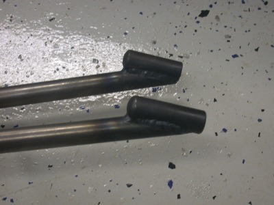
The frame needs to be at the riding height before you can set the front end caster. We have set up the frame using jackstands and set the rake we want in the finished car. With the front end set up and the caster set we move to locating the hairpin mounts on the frame rails. We want the hairpins to be mounted on each frame rail and still maintain the correct caster. With the front end squared in the frame, the caster set we actually shortened the top bar of each hairpin. We cut 1/2” off the length to achieve the location point we wanted on each frame rail. |
|
|
|
|
|
|
|
|
|
|
|
 |
|||||||||
 |
|||||||||
 |
|||||||||
|
With the locations marked we center drill all 4 locations. With the center drill as a pilot, each location is hole sawed. |
|||||||||
 |
|||||||||
 |
|||||||||
|
With the inserts in place in each frame rail, we mount the end of the hairpin with a long piece of threaded or solid 5/8” rod. |
|
|
|
|
|
|
|
|
|
|
|
|
|
|
 |
||||||||||||
 |
||||||||||||
 |
||||||||||||
|
Take a close look behind the rod end on the frame rail. That’s our C.P. teardrop. It’s a polished aluminum casting that mounts behind the mounting rod ends on hairpins and front 4-bars. You can check them out on our web site atwww.cruisinproducts.com |
||||||||||||
 |
||||||||||||
 |
||||||||||||
 |
||||||||||||
|
Check out our products at www.cruisinproducts.com !!! |
||||||||||||
|
Segment 9: June 4, 2004 Let me first correct my mistake in the last segment. The front locating bars are hairpins and not ladder bars. But most everyone knew that already. It’s nice to know that someone is reading this series. I have received a lot of great e-mails so far on the series. A lot of questions and have added some new customers from the build up of the frame. |
|
|
|
|
|
|
|
|
|
|
 |
||||||||
 |
||||||||
|
Now for something new. Curbside Hotrod Parts, Boyd Singer and company have come up with a new twist on the old ladder bars. At first glance one may not see the difference, but look close and you will see the advantage of this new design. |
||||||||
 |
||||||||
 |
||||||||
 |
||||||||
 |
||||||||
|
All you keen eyed builders noticed that the frame didn’t have a rear cross-member, only a piece of tubing to hold the tails of the frame. Since we are slamming this roadster with a flat model A front cross-member if only seems right to step the rear cross-member. The step in the rear cross-member will also have the top mount for the rear coil-over shocks. In the picture you can see the step is actually higher than the top of the rear frame rails. Keep in mind the housing brackets have three vertical shock mount locations. |
||||||||||
 |
||||||||||
 |
||||||||||
|
The front ladder bar mounts in the frame come off a 1 1/2” tube that is located off the top main rails in the X member. With the trans in the frame you can see the relationship of the mounting locations. With the trans removed we installed the ladder bars in the front mounts. It gives you a feel for how fast we can fill tight spaces. |
||||||||||
 |
||||||||||
 |
||||||||||
|
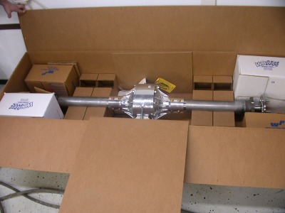
The rear coil-overs and spacer mounts are more parts from The Deuce Factory. These shocks are All American polished aluminum body with powder coated springs. This pair is the shorter 13” length that is available. These shocks also have an adjustable dampening valve. A real plus when you are fine tuning the rear suspension. We mount the rear end in place and hang the rear coil-over shocks. You know when these chassis start coming together it’s a beautiful thing. |
||||||||||
 |
||||||||||
 |
||||||||||
|
With the rear end installed we need a rear panhard bar to keep things in place. Before we install the rear panhard bar, the pinion angle must be set. With the new ladder bars you adjust the pinion angle just like a rear parallel 4-bar. |
|
|
|
|
|
|
|
|
|
|
|
|
|
 |
|||||||||||
 |
|||||||||||
 |
|||||||||||
|
With the rear end mounted in the frame, what can I say. A picture is truly worth a thousand words. |
|||||||||||
 |
|||||||||||
|
The final color rendering of the roadster project arrived from Mutant Art, Gary Constable of Louisville, KY. Gary helped us out with a special build project we hope to bring to you after we move to our new location. Gary has really done another outstanding job with the roadster. |
|||||||||||
 |
|||||||||||
|
Check out our products at www.cruisinproducts.com !!! |
|||||||||||
|
Segment 10: June 30, 2004 We have been able to utilize the services and products of many sponsors of the roadster project and we want to introduce you to Federal Industrial Services, sandblasting and metalizing specialists. Mike Hadwin and his crew are the good people who prepared all the components parts to be powder coated. We have used their services in the past for small parts and to blast complete frames. If you are in the Detroit area be sure to check them when you need metal preparation. They have two locations, one on the east side and the one we use in Livonia, MI. |
|
|
|
|
|
|
|
 |
|||||
 |
|||||
|
Segment 11: June 30, 2004 This roadster project could not have happened without the support from all sponsor companies. Last year at the NSRA Nationals this idea blossomed into the build project you have been able to follow along on HotRodHotLine.com. |
|
|
|
|
|
|
|
|
|
 |
|||||||
 |
|||||||
|
Check out our products at www.cruisinproducts.com !!! |
|||||||
|
Segment 12: July 6, 2004 With the chassis now bolted together and a couple of shows under our belt, I wanted to get the chassis back into the shop. |
|
|
|
 |
|
 |
|
|
|
|
|
The front plate in the gusset system will be welded to the front outside vertical mounting bracket of the 04 Ladder Bar. |
|
|
|
|
|
 |
|||
 |
|||
|
Now that the front and top plates of the gusset system have been tacked in place we will install the rear gusset plate. It gives strength to the rear of the front 04 ladder bar mount. It ties in the top crossbar tube to the top and bottom main rails in the X member. The directional strength it adds will keep the front mount from folding under torsional movement of the ladder bar. |
|
|
|
|
|
|
|
|
|
|
|
 |
|||||||||
|
With the gusset system tacked in place the only thing left to do is metal finish the installation. |
|||||||||
 |
|||||||||
 |
|||||||||
 |
|||||||||
 |
|||||||||
 |
|||||||||
|
Segment 13: July 16, 2004 We have the chassis back in the shop and want to install the engine and trans. The engine mounts are tubular with a urethane bushing to absorb vibrations. The frame mounts are simple and flank the bushing. A 1/2” bolt passes through the mount and the bushing. We added our own touch to top off the two mounts brackets. |
|
|
|
|
|
|
|
|
|
 |
|||||||
 |
|||||||
|
The small block Chevy engine we plan to use was in need of some aftermarket exhaust headers. While attending the Hot Rod and Restoration Show in Indy earlier this year Sanderson Headers came through with a set of their coated headers. |
|||||||
|
Sorry, it’s a little blurry! |
|||||||
 |
|||||||
 |
|||||||
 |
|||||||
|
Segment 14: July 23, 2004 We are very happy that Garlits Performance Products will help along the project with their IN 600 Street Induction product. This unit gives us the Hilborn injected look with the drivability of a carbureted ride. The unit arrived in a week after making the deal with Alan Shadwick of www.alsblowers.com. As you can see in the following photos the unit is quite impressive. |
|
|
|
 |
|
 |
|
|
|
|
|
The unit has to be assembled and comes with easy to follow instructions. We started on the assembly late one night and worked through the night to achieve the visual effect you see in the pictures. |
|
|
|
|
|
|
|
 |
|||||
 |
|||||
 |
|||||
|
SAFETY BAR INSTALL
Segment 18: August 18, 2004 While the chassis is on the show tour we have made one of the upgrades to the roadster body. Years ago, like 20, but who’s counting, we were actually building fiberglass ‘32 Ford bodies. We were mentored by the best in the industry to build as good a body as possible. The bodies we had built were steel reinforced with a complete steel tube substructure. |
|
|
|
|
|
|
|
 |
|||||
|
After the 3/4” steel tubing has been removed, we prep the B pillar plates for the new installation. The areas where the new 1.5” round tubing will be welded into the B pillar plates are marked and ground clean. There are three locations where the new reinforcement structure will weld to each B pillar plate. A floor plate welds to the bottom of each B pillar plate and runs back to the wheel well area. That plate also has two body hole locations that body mounting bolts will pass through to the frame. The weld at the bottom of the B pillar plates and the two body hole locations provide a solid base for the new steel tube safety bar structure. |
|||||
 |
|||||
 |
|||||
 |
|||||
|
Once the new safety bar is completely installed the added B pillar strength is quite apparent. The new structure also is welded to the remaining 3/4” steel structure still in the body. The new safety bar structure also provides points for seat belt attachment off the lower bottom plates. The horizontal safety bars offers mounting points for a fuel tank mounting behind the seating area. |
|
|
|
|
|
|
|
 |
|||||
|
Segment 16: September 3, 2004 The body we are using in this build is a Rats Glass ‘32 Roadster. The Roadster has a few special features. The doors are 3” longer. The cockpit or seating area is also 3” longer. It has a rear rolled pan. The stock eyebrow on the cowl has been removed. Because of that fact a stock windshield assembly will not work with this new designed body. The popular design Duvall windscreen will fit fine on the body. Our choice for the Duvall windscreen is Grant Engineering. |
|
|
|
|
|
|
|
 |
|||||
 |
|||||
|
The first thing we did after removing the windscreen and checking the instructions was to set the windscreen on the cowl. After lining it up we marked the center and the outer edges of the casting locations on the cowl. |
|||||
 |
|||||
 |
|||||
 |
|||||
|
To illustrate the outline better than the pencil tracing we traced the outline with a magic marker. |
|
|
|
|
|
|
|
 |
|||||
 |
|||||
 |
|||||
|
The marks are now used to locate the stud holes on the tape. Measure the distance back from the leading edge on the casting for each location. Transfer the locations to the tape. Measure the hole locations and check them twice. These locations will be drilled through the cowl. |
|||||
 |
|||||
 |
|||||
 |
|||||
|
The locations are drilled with a small drill first. Step drill the holes to a size just a little larger than the stud. Once you have completed the drilling process, remove the tape. |
|||||
 |
|||||
 |
|||||
|
Install all the studs except the last ones at each end of the casting. You will have to install them from inside the cowl after the windscreen has been located on the cowl. |
|||||
 |
|||||
 |
|||||
|
With the windscreen in place and secured with a couple of washers and nyloc nuts, install the last outside studs from inside the cowl. In the pictures you will see how the installation looks from inside of the cowl area. |
|
|
|
|
|
 |
|||
 |
|||
 |
|||
|
Segment 17; August 19, 2005 It has been quite a while since our last segment. The response to this build series has resulted in a workload that we never could have imagined. Customer orders come first and the Roadster project was sidelined. |
|||||
 |
|||||
|
The Rats Glass roadster body has a raised area in the rear of the floor behind the seating area in the trunk. It allows for a higher rear crossmember to be used in the chassis as well |
|||||
 |
|||||
 |
|||||
|
|
|
|
With the rear floor opened up the body now sits on the chassis. We lined up the body |
|
|
|
|
|
 |
|||
|
When we finished with the pilot holes we step drill the pilot holes until we have the correct hole size for the tap we need. To make this proceedure easier we move the body |
|||
 |
|||
 |
|||
 |
|||
 |
|||
|
|
|
|
With all the holes tapped, we put the body back on the chassis. Note of caution.All composite bodies are not built the same. Some have steel reinforcing and some do not.You should evaluate the strength of the body you are working with before you move it about as we have to tap the mounting holes in the frame rails. |
|
|
|
|
|
 |
|||
|
Segment 18: Septmber 15, 2005 Well, Nats North is approaching very soon so this segment will be short.We want to mount the radiator, grill shell and insert. |
||||||||||||||
 |
||||||||||||||
|
As you can see in the pictures the shell and insert |
||||||||||||||
 |
||||||||||||||
|
The radiator should have some protection so we have cut out a piece of heavy cardboard to cover backside or exposed area of the radiator. |
||||||||||||||
 |
||||||||||||||
|
The radiator we are using is 2" shorter than a stock radiator for a 32. We use a short radiators so we can mount the radiator at a certain height to give the car the look we want.Nothing looks worse than a radiator that is mounted too high and the hood line looks as if it were going up the grill shell, not down to the grill shell. To achieve the correct looking height we have fabricated a couple aluminum mounting blocks.The blocks will be placed under the radiator mounting tabs.The tabs themselves have a 1" drop .With the flat front crossmember we are using spacers are a necessity. |
||||||||||||||
 |
||||||||||||||
 |
||||||||||||||
 |
||||||||||||||
 |
||||||||||||||
|
With the radiator mounted we can check the look of the car by placing masking tape from the radiator shell to the cowl . We do this spacing them apart to give us a visual check of the proper height for the radiator . We do plan to run a hood on this car and want to achieve the proper rake for the car. |
||||||||||||||
 |
||||||||||||||
|
Segment 19: November 28, 2005 March Performance Pulleys helped us out with a set of their serpentine pulleys for the roadster project. The 6 rib design set is for the crank, water pump and the alternator. Finished with a clear powder coating these pulleys will look great long after being installed. |
||||||
 |
||||||
 |
||||||
|
Wanting to compliment the finish on the pulleys with stainless fasteners I called Bob Ainsworth. You might have seen him at N.S.R.A. shows this past year selling bolts,valve covers and other assorted parts. To my surprise ,Bob grabbed his bolt bins and drove over to give me a hand. Actually, Bob really got into the task at hand. |
||||||
 |
||||||
 |
||||||
|
The initial mounting of the pulleys showed we needed a spacer to properly line up the water pump and crank pulleys. I machined a spacer for the water pump pulley to achieve the proper alignment. Once installed the pulleys were in line. |
||||||
 |
||||||
 |
||||||
 |
||||||
|
Randy Killingbeck from March Performance Pulleys and Brackets really came through with the pulley set we wanted for the roadster build. March builds pulleys and brackets for every popular engine. They also build brackets sold by many of the companies in the aftermarket performance field. Be sure to check them out on the web or at the next major show. Check the sponsor page for their contact information. |
||||||
|
Segment 20: December 29, 2005 We have been very busy and haven't had the time to do much on the roadster build lately. Tom and I took the time today to show the components and what we did to mount our steering in the 32 roadster project. All of our components came from Ididit. We have the standard steel 32" steel column, the standard size aluminum adaptor ( they also make a shorter one ), the Lecarra steering wheel, stainless Borgenson joints and a length of double D stainless shaft. We fabricated an aluminum finish plate that will cover the hole in the firewall and also provide the mounting studs for the column. We drilled and tapped the back of the aluminum finish plate for two studs that will pass through the firewall and provide the mounting pointd for the tabs we welded to the column. Check out the pictures . |
|||
 |
|||
 |
|||
 |
|||
 |
|||
|
|
|
|
We tried a couple of different locations before we were happy with the steering column height and angle. We made the opening in the firewall a little larger than the column so we could move the column as the components were installed. The hole location in the picture is actually our second choice as we had located the first hole to low. The first hole was filled in with fiberglass mat , sanded flat and painted flat black. here is no one definite location for a column since the space available is determined by the height and location of the engine and the engine mounts. Another consideration is the brake pedal location. Since we haven't decided on the mounting location of the brake master cylinder yet we left ample room when we made the final position of the steering column for the brake pedal. We had to add a flat steel plate to the steel tube substructure in the upper cowl area of the roadster body. The flat plate has 4 mounting slots machined into it for adjustment of the steering column mount. That mount is an Ididit polished aluminum swivel mount. It has two mounting studs that pass up through the flat plate we welded behind the dash. A couple flat washers, lock washers and nuts and the swivel mount is in place. |
|
|
|
|
|
 |
|||
 |
|||
|
With the upper steering column mount in place we have determined the length of stainless shaft we need to join the two steering joints. The joints must be in phase for the steering to work correctly. The joints to be in phase must be able to flex in the same plane. You can see the alignment in the picture. Something we had to do also was radius our gusset plates on the engine mount for the joint to clear. Both front and rear gussets were radiused for the proper clearance of the steering joint. We want the shaft assemble to be as close as possible to the headers and still be within the working angles of the joints. The shaft appears closer in the picture than it really is because of the camera angle. There is a space of about 1/2" between the shaft and the header. |
||||||
 |
||||||
 |
||||||
 |
||||||
 |
||||||
|
Remember the finish plate we made for the column, it was slipped over the column before we installed the steering joints and stainless steel shaft. You can see Tom positioning the plate on the firewall. The two studs that pass through the firewall are the mounting points for the tabs we have welded to the steering column. Tom installs the flat washer, internal ring lock washer and nut on the inside of the firewall on one of the steering column tabs. He will leave the assembly loose until the upper mount is tightened. All mounting points are checked for final alignment and when we are satisfied with the angle and location we tighten all the fasteners. The installation of the column from the engine side of the firewall can be seen in the final picture. |
||||||
 |
||||||
 |
||||||
 |
||||||
 |
||||||
 |
||||||
 |
||||||
|
With the column in place the steering wheel adaptor can be installed. The first thing you need to do is install the spring loaded horn hot lead off the column shaft assembly. It simply pushes into the plastic mount and with a quarter turn is secured in place. The wire is fed through the hole found in the steering wheel adaptor, next to the center splined hole. Once the adaptor is fitted on the spline tighten the nut on the column shaft. The steering wheel now can be located and installed on the adaptor. It is fastened by a number of small flat head fasteners that are equally spaced in a bolt circle. Once that is finished the horn button, another product from Ididit, can be installed. The complete assembly installed, column ,steering wheel adaptor, steering wheel and horn button. One more component system installed in the 32 roadster project. Good job Tom, no you don't get Holiday pay. |
|||||
 |
|||||
 |
|||||
 |
|||||
 |
|||||
 |
|||||
 |
|||||
|
Size Does Matter Segment 21: September 6, 2006 Attending the Goodguys Nationals this past July in Columbus Oh we were dealt a hand of fate. Directly across from our booth was noneother than Team III Wheels. You know , ET wheels, Classic Five, Fueler, LT-III and Gasser . |
|
|
|
|
|
|
|
 |
|||||
|
After mounting the larger tire/ wheel combo the roadster had a stance with a little too much rake. The rear suspension was built with 3 point lower coil-over shock mounts, that allows changing the height of the car simply by moving the lower shock mounting bolt to another one of the three mounting holes found in the lower shock mounts. |
|||||
 |
|||||
 |
|||||
|
As you can see from the two photos, the before and after shot of the tire and wheel combo is quite dramatic. Also with the dropping of the rear suspension ,the rake of the car is more appealing. The combination of 14" tires and wheels in the front and 16" tires and wheels in the rear achieves that ever elusive curb appeal we all struggle to achieve. |
|||||
 |
|||||
 |
|||||
|
Segment 22: July 2007 Lynn, my wife, and I were lucky enough to attend this years Grand National Roadster Show in Pomona, CA. We were there to help promote the Deuce at 75 show that will be held in Dearborn MI 9th - 12th of August, 2007. The GNRS was the kick off celebration of the 32 Fords 75th anniversary and the gathering of the most significant 32 Fords that have influenced the streetrodding culture that so many of us enjoy. It was a once in a lifetime event. |
|
|
|
 |
|
 |
|
 |
|
 |
|
 |
|
 |
|
 |
|