Updating To An Electrical Gauge Package
by Jim Clark, The Hot Rod M.D.
The original gauge package that I selected for my roadster in the 1970s consisted of manual gauges for the oil pressure, water temperature, and speedometer readings because I was using a magneto in my Buick Nailhead-powered roadster. I chose them because magnetos and electrical gauges don’t play well together. I also had an ammeter with a 50-amp maximum range that is no longer adequate for my new 65-amp alternator. These factors and the change to a new Crane conversion-equipped, Russell Martin rebuilt Buick distributor called for the update to some new gauges.
I ran mechanical gauges in my small-block Chevy-powered Deuce Vicky for eight years without any problems. They survived the drive from California to New York in ’62 and the return drive when I moved back to California in ’65. However, I didn’t like the large hole that I had to make in the firewall to route the copper tube for the oil pressure gauge and thermo-couple for the temperature gauge. My highboy has nothing but throttle linkage poking through the firewall so I wanted to avoid routing anything else through it.
Retaining the classic looks of the VDO Cockpit series gauges that the car was designed to have in the vintage gauge panel was important. Fortunately I was able to replace the mechanical gauges with a full set of modern VDO Cockpit series electrical gauges. The new gauges install more securely with the VDO Spin-Lok mounting clamps instead of the old style U-shaped clamps. One-quarter inch spade-connectors supplied with the instrument kit wiring harness made installation simple and easily removable should the need arise.
The biggest benefit derived from the change has to be the fully programmable VDO speedometer. Instead of running a cable from the manual speedometer to the transmission this unit connects to the hall-effect sensor screwed onto the transmission cable-drive to the speedometer via a three-wire cable that is much easier to route. Once installed the new VDO speedometer can be programmed to suit the vehicle and reprogrammed easily should any changes be made in tire size or gearing. No multipliers or adapters are needed to do this like is needed with mechanical units.
Instructions included with the gauge kit and wiring harness are pretty complete and should make installation relatively easy. Everything is not plug-and-play though because equipment in each vehicle can vary widely so some modifications need to be made to accommodate your specific vehicle. The accompanying photos show the differences between the two gauge sets and the modifications that were necessary to install them in my roadster. You may find that you also need to make some of these same alterations. A full line of VDO gauges are available at www.Yogi’s.com.

Since I was replacing all but the fuel gauge I chose to buy the five-gauge kit instead of buying individual gauges separately. This is the new VDO Cockpit series kit with 3-1/8 inch programmable speedometer and a GM Hall-Effect sensor for my Turbo 400, Switch-Pitch Buick transmission. Kit can be ordered with a 3-3/8 inch diameter speedometer and connections for other transmission applications.

The old and new water temperature gauges both look the same except for the change in the sweep of the needle across the face instead of in a circular motion. Mounting is different with the threaded VDO Spin-Lok clamp instead of the U-clamp for the old style gauges.

Mechanical temperature gauge is equipped with a long thermo-couple that inserts into a fitting on the engine and transmits the temperature variation directly to the gauge via the shielded tube. They work fine but the new electrical gauge eliminated the need for a hole through the firewall and the storing of a loop of excess tubing under the dash.

New oil pressure gauge has the same pressure range as the mechanical gauge but with the new sweep of the needle across the face instead of in a circular motion.

Mechanical oil pressure gauge is connected to the engine oil galley via a nylon or copper line requiring that a hole be made in the firewall to route the tube through. I had mechanical gauges in my ’32 Ford Vicky and experienced no problems with them but the installation of the new electrical one is much easier and cleaner.
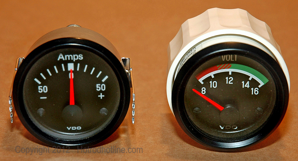
My original set of gauges included a 50-amp ammeter that was more than adequate at the time but the addition of a 65-amp alternator recently made the 50-amp units capacity to low. Most new vehicles are not equipped with an ammeter so a VDO Cockpit series ammeter of sufficient capacity is not available. I chose to switch to this VDO Cockpit series voltmeter.

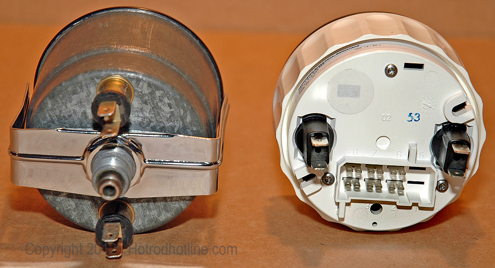
Some people consider ammeters as potential fire hazards, because there are two high-current-flow terminals exposed at the rear of the gauge. Voltmeters only have a 12-volt power supply terminal and ground terminal at the rear making the potential hazard much less of a concern.

Face on the fuel gauge is almost identical for both the early and late gauges, with the exception of changing the word “Tank” to “Fuel”.

New fuel gauge has three terminals. At the left is input for 12-volts, bottom terminal is for ground and right terminal is for the signal from the tank sending-unit. Changing the sending unit in the tank was necessary because the signal output (empty reads 10-ohms, full reads 180-ohms) has to be compatible with the new gauge.

Both the mechanical and electronic speedometers cover the same speed ranges and feature an odometer and trip meter. The electronic speedometer is fully programmable and displays odometer and trip meter readings via a digital display.
Mechanical speedometer requires a drive cable that runs from behind the dash out to the connection on the transmission. Then the gears have to be changed to compensate for any variation in tire size or other changes made that differ from the original vehicles specifications. The electronic speedometer is fully programmable by the owner and connects via a simple three-wire cable attached to a Hall-Effect sensor installed on the transmission.

The new VDO gauge kit included an oil pressure sender, water temperature sender, brass thread-adapters for a variety of possible applications, four connectors for the gauges, one connector for the electronic speedometer and an assortment of terminals needed to complete the connections.

I also purchased the VDO six-instrument wiring harness kit (#240 030) to make the connection of the gauges simpler and removable if, necessary, by unplugging the connections rather than disconnecting more permanent types of connections. Black and white wires are for the instrument lights and have insulated spade ends on them. Orange wires are for the 12-volt power source to gauges and other wires are for individual gauge functions. Extra set of unconnected wires is for a tachometer, something that I am not including in my gauge array.

This is the modified harness after adding the connectors for the gauges and making butt connections (blue) to remove the extra wires for the tachometer. Yellow with a blue stripe, butt connectors are step-down connectors that allow the crimping of two 14-16 gauge wires in one end and one 14-16 gauge wire in the other (blue) end. Using the correct size of butt connector is important because improper crimps create potentially dangerous connections. Additional wires next to the plug are added for the speedometer and gauge functions not included in the basic harness.

This photo shows the harness connected to the gauges on the bench because it would be difficult to see how the connections were made after the gauges are mounted into the dash. Instructions included with the gauges and harness kit tell anyone with some basic wiring knowledge how to make the necessary connections.

Stripping the insulation on the wires and making crimp connections correctly is critical to creating a safe and functional electrical system. At the left are two wire-stripping tools. One is a more precise tool (blue) that strips a variety of wire sizes without cutting any strands and the other one (red) is a less expensive tool that requires more care when stripping insulation to avoid wire damage. The three crimping tools shown are: a precise crimper with a controlled ratcheting crimp, cheap general-purpose crimper/cutter and a specialty crimper for making crimps on connectors that insert into connector plugs.

This W-style crimper is needed to make the folded-style crimp connection on the pins that are supplied for insertion into the connector plugs. Standard style crimper used on butt connectors will not make this type of crimp. Inexpensive crimpers like this are available at any good auto parts store.

This hall-effect sensor connects to the speedometer outlet on my GM transmission. Cable plugs-on to sensor and is routed to the rear of the speedometer via the three-wire connection. Kits with necessary connections for other applications are available from VDO through Yogi’s.com, and other suppliers.

Water temperature sensor supplied with the kit threads into the engine directly or via the adapter provided. Single wire routes to the gauge via the wiring harness installed behind the dash.

Oil pressure sender provided in the kit screws into the oil galley where the original Buick sender had been located. Three different size thread adapters are included to accommodate other engine applications. One wire is all that is needed to send the signal to the gauge.

Fuel gauge sender unit for the new electrical gauge included with the kit has a two-part extension arm that adjusts to accommodate the variable depth of different fuel tanks. Also includes new style float and a rubber gasket for the standard 5-hole mounting plate.

My original ’32 Ford gas tank is only 8-inches deep so the lower segment of the extension arm is removed and the float pivot assembly reinstalled at 4-inches per the included table that provides pivot assembly and float arm length information, based on tank depth. However, the new float / sender mechanism is too large of a diameter to fit through the mounting hole in my ’32 Tank. Fortunately I am able to use the early fuel gauge and sender that I had already modified (See: Installing a Fuel Gauge and Sender in other Hot Rod MD article) for use in my smaller diameter 6-hole mounting flange in the tank.

This shot up under the dash shows the gauge harness installed onto the mounted gauges. Spade-connectors make the installation easier and allow for future maintenance without removing everything, if necessary.

This is the gauge panel with a full set of mechanical type VDO Cockpit series gauges that was acquired and installed in the ‘70s.

Here is the finished dash with the new electrical style VDO Cockpit series gauges. The original styling was maintained but with significant upgrades like the programmable speedometer that eliminated the need for a speedometer cable and a change from an ammeter to a voltmeter.